
 By Dave Coleman
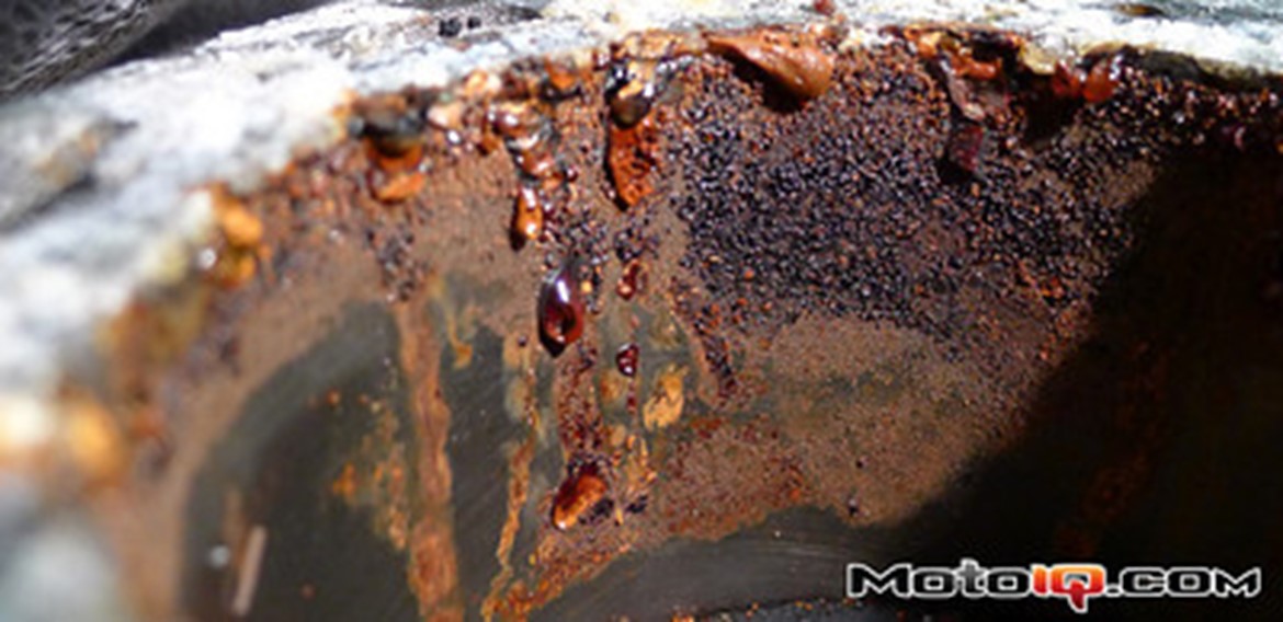
The last installment of Project Silvia was a story of tragedy. A tempting, but ultimately unnecessary attempt to broaden my powerband, coupled with a string of bad luck, and my own staggeringly shortsighted outdoor storage strategy had reduced my stone-reliable SR20DET into a worthless, rusty mess.
So at the end of the last installment, I changed my strategy. Instead of a simple S13-to-S14 head swap, this was now a full balls-to-the wall rebuild to get the most output from this engine I possibly could. The most, with three very important caveats.
When I built Project Silvia the first time, there was an opportunity to install a race gas map. Clark Steppler, the Nissan ECU mastermind at Jim Wolf Technology, had rigged up a way to switch between 4 different fuel and timing maps on a stock Nissan ECU. We could easily have tuned one map for the recently-introduced 91-octane distilled bum sweat we run our cars on in California, and another for 100-octane unleaded. But I was never even tempted by this idea. The thought of paying for a full tank of $5/gallon race gas was just too outrageous!
A few months ago, 87 octane was $5/gallon (its dropped nearly a dollar since then), so it should come as no surprise that race gas is still off the menu. So that’s caveat #1: This engine will be built around a diet of 91 octane. That means we’ll be doing everything possible to keep this thing from knocking, and we’ll be looking for power in places that don’t require higher cylinder pressures–like friction reduction.
#2 is simple. I am a mammal, and as such, I’m smart enough not to shit on my own dinner plate, or to poison my own air. Well, at least not any more than is absolutely necessary to keep myself entertained. So this engine will breathe through a cat.
And finally, #3 is is that we must define “the most” very carefully. Getting the most out of this engine does not mean making the biggest peak power number. It means a big, wide, useable powerband. If peak power must be sacrificed to improve responsiveness and torque, I just might do it. The crude VVT system on the S14 head should make that unnecessary, though.
Ok, so now that we all understand the goals, how the hell am I going to pull it off? Every time I touch this engine, I’m overcome by an urge to machine it with a file, or weld some Mexican Dodge parts to it. My instincts are so thoroughly ghetto, I’m not sure I can trust myself to go full Kojima on this thing. So I’ve assembled a team of detail-obsessed nerds to look over my shoulder and slap my hand every time I reach for the zip ties.
Clark Steppler has been my go-to Nissan nerd for years. I always turn to Clark first for advice on nonsense like this, and one of his first pieces of advice on this engine surprised me. “Don’t assemble it yourself.” The thought of not building it myself never even crossed my mind. I always build my own engines (for better or worse), but perhaps Clark knows me better than I know myself. Instead, he suggested I turn to Nick Hunter at 5523 Motorsports to screw it together. My initial hesitation evaporated as he started telling me about Nick’s attention to detail, including strange little tricks like how he hand cuts oiling grooves in the main bearing support to bring SR20s up to the same spec as the rare Pulsar GTi-R engines. My engine could use a bit of that obsessive attention to detail, and it sure isn’t gonna get it from me!
Nick is also the guy who heroically built a backup VQ35DETT for Dai Yoshihara’s drift car on only 3 days notice, in his living room, when the original engine blew a head gasket during demo runs in Abu Dhabi and had to be running again a few weeks later in Qatar. Yeah, Ok, I like this guy… Mine will be one of the first batch of engines built in 5523 Motorsports’ fancy new clean room, so we won’t have to worry about getting silver engine paint on his La-Z-Boy.
The third member of my ghettocharging recovery support group is MotoIQ’s own Chuck Johnson. Chuck’s day job at JE Pistons focuses his nerdly obsession at the bouncy bits, and that’s where this project finally gets going. Parts catalogs are an engineer’s best friend, and it was reading his favorite parts catalogs a few years ago that Chuck figured out the Honda H22 long-rod trick that has spread through the MotoIQ garages like a virus.
Squeezing a longer connecting rod into an engine is a relatively common trick for extending the rev range of an engine. The benefits of longer connecting rods are simple, if a little tricky to grasp at first blush. There are several things going on when you change the length of the connecting rod. Most of them are subtle, and some of them are good. 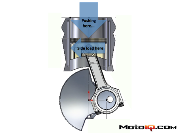
Less friction: Look at this diagram of a reciprocating group with the crank at 90 degrees. When there’s some force pushing down on the piston, the angle of the connecting rod ensures there will be a reaction force shoving the piston into the cylinder wall. A longer connecting rod will result in a slightly shallower connecting rod angle. Shallower angle means less side load, which means less piston to wall friction.
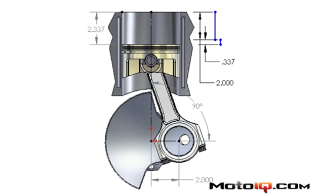
Lower piston acceleration: The actual motion equations explaining piston motion are all mathy and annoying, but there’s a shortcut to understanding how a long rod results in less acceleration. If we put some arbitrary dimensions on this rotating group diagram (arbitrary because those were the numbers that were already there when I stole this image from the internets) you can see that the top half of the stroke is bigger than the bottom half. This diagram shows a 4″ stroke, so the halfway point on the stroke is 2″, but the piston position when the crank is halfway through the stroke is already to 2.337″.
The reason is simple, shoving the big end of the rod sideways 2 inches pulls the piston down 0.337″ (with this particular rod length).
Now, if the rod were longer, we’d have that shallower rod angle, and that shallower angle would pull the piston down slightly less.
Since the first 90 degrees of crank rotation move the piston farther than the second 90 degrees, the highest acceleration obviously has to be in the top half of the stroke, where the piston covers more ground in less time. And all else being equal, a piston that has to get from TDC to 2.337″ down the bore will have to accelerate slightly harder and go slightly faster than one that doesn’t have to go quite as far.
So, simple as that. Longer rod = lower peak acceleration.
More dwell time at TDC: This effect isn’t always good news, but for the same reason that there’s lower acceleration, a longer rod means the piston spends just a little more time hanging out near top dead center. This can have varying effects on scavenging and charge motion that can be better or worse depending on your cam profiles. You’ve really got to spend a lot of time building and dyno testing different versions of the same engine before you’ve got a good sense of whether this effect is a good from a breathing standpoint.
There is a chance this is bad from a knock standpoint, which is a pretty damn important standpoint for this build. If the engine is near the knock limit, more time spent near peak cylinder pressures is more time for spontaneous, uncontrolled combustion to start. The faster the piston can get on with the business of moving down the bore and reducing pressures, the less chance there is to have a knock event. This is why high-rpm engines can get away with higher compression and/or more boost, and why motorcycle engines almost never knock. At high rpm, peak cylinder pressure goes by so fast there isn’t time for the chemistry to go bad.
So there are two good reasons we’re going with a longer rod, and one little nagging doubt that it might be a bad idea…
Now, the actual parts themselves: Obviously you can’t just stuff a longer rod in an engine and use the same piston. Do that, and the piston will move up by the same amount you lengthened the rod. Every millimeter you add to the rod has to be matched by moving the wrist pin a millimeter higher in the piston. If you’re building a race engine and you’ve got lots of money, you get longer rods by just having custom rods and custom pistons made. You can do this for any engine, it just takes money.
The epiphany Chuck found with the Honda H22 rod is that an off-the-shelf Honda rod is almost dimensionally ideal for being a long-rod SR20 rod. Being able to use off-the-shelf parts for at least half this equation brings it into the realm of the attainable.
Obviously, if we put a stock Honda rod in an SR20DET, the spindly little Honda rod would tie itself into a pretzel the first time you came up on boost. But an off-the-shelf, mass-produced, reasonably-priced K1 rod that’s been forged and shot peened to perfection is another story altogether.
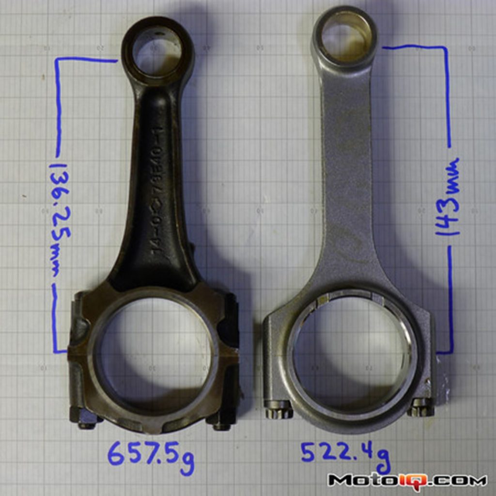
The factory SR20 rods are already insanely beefy, especially considering the 140hp they supported in U.S. cars and the still meager 205 hp they supported in early SR20DETs. The stock rods are already forged steel, but they’re forged in a simple, cost-effective I-beam shape.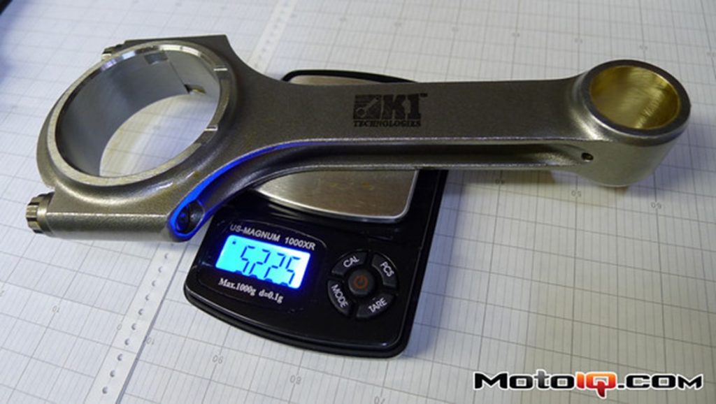
The K1 rods are forged in an H-beam shape, which concentrates material where it’s needed most for a better strength to weight ratio. H-beam forging takes additional forging steps to punch out the deep grooves down the sides, but the benefit is obvious when you look at the 135 grams saved vs. the stock rod.
The H22 uses the same 48mm rod bearing diameter, but is slightly wider (note the small gap above the SR rod). Narrowing the rods is a simple machine shop operation.
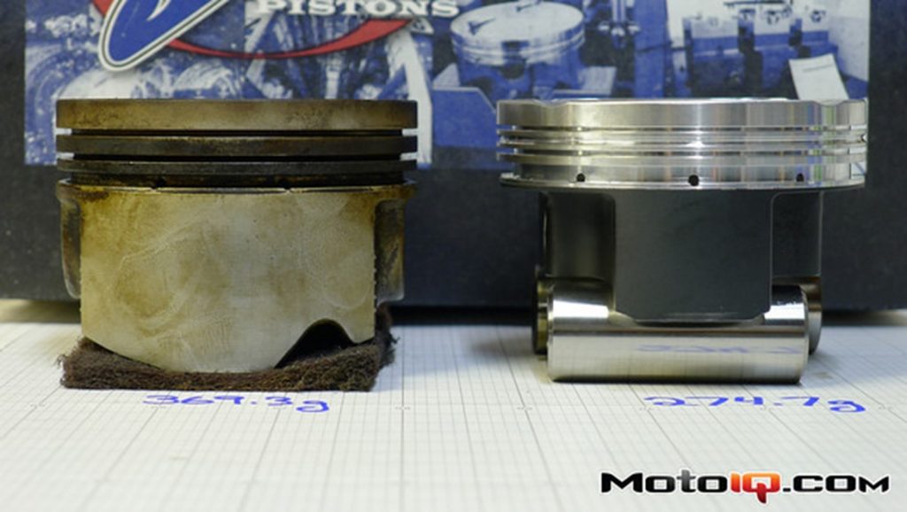
You’ll have to excuse the sloppy photo manipulation I did to properly align the tops of the pistons in the shot above. These two photos are actually two halves of the same photo, but the relevant fixed dimension is the top of the piston, not the graph paper they’re sitting on. Anyhoo… Look at the wrist pin bore on the two pistons and you’ll see how the custom JE piston has its pin shoved up 6.75mm to accommodate the longer rod. This puts the bore deep into the oil ring groove, but as long as the bottom plate of the oil ring is installed so its gap isn’t in this pin bore, you can actually get away with this. The oil ring groove is cut extra-wide to make room for this additional bottom plate.
This is the practical limit for moving the pin up. Any more, and you effectively start weakening the piston when you either cut into the land supporting the 2nd compression ring, or pushing the whole ring pack up, reducing the material above the first compression ring. So yeah, it was kinda lucky the H22 rod was just the right length…
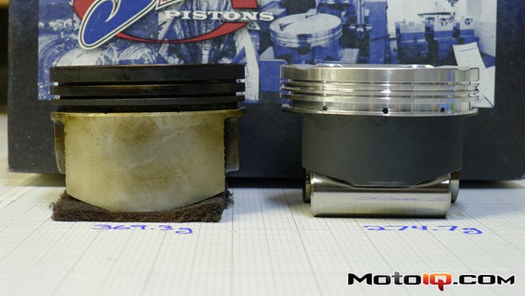
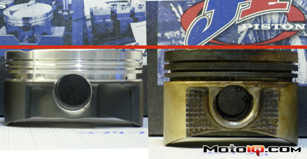
In addition to the friction reduction from the long K1 rod, the JE pistons further reduce friction with a whole bag of tricks. First, notice how much shorter the skirt is. That’s about 1/3 less surface area dragging on the cylinder wall. Even more important, the black finish is a low-friction coating. Actually, the fact that the SR20 doesn’t have such a coating is a real clue what a dinosaur the SR20 is getting to be. Pretty much all modern production engines use skirt coatings now, including the later, more technologically advanced VE versions of the SR family.
The big difference, of course, is on the other skirt. The notch in the stock skirt is to clear the piston oil squirter. The JE’s mini-skirt is so small, though, it doesn’t even get close enough to need the squirter notch. So what’s with the asymmetrical skirts? Simple:
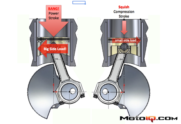
The skirts are asymmetrical because the loads on the skirts are asymmetrical. Think about it. The piston sees its biggest compressive load during the power stroke. That big bang of pressure pushing down on the piston always happens when the rod is offset in the same direction. As a result, the major thrust load into the cylinder wall is always on the same side of the piston. When the piston is on the compression stroke, the significantly lower compression pressure happens with the rod on the other side, putting a smaller side load on the minor thrust side of the piston. JE simply designs each skirt to be only as big as needed for the load it will see.
Kinda makes you wonder why all pistons aren’t designed this way, doesn’t it?
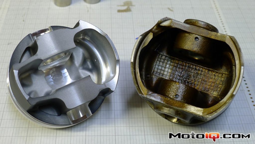
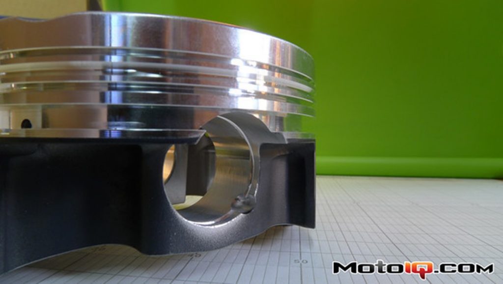
Look at the underside of the JE pistons and you can see some machining marks just above the wrist pin. This was a special machining step to prevent contact with the high-mounted connecting rod. This design change had a few knock-on effects…
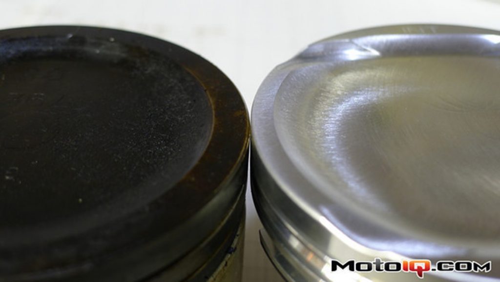
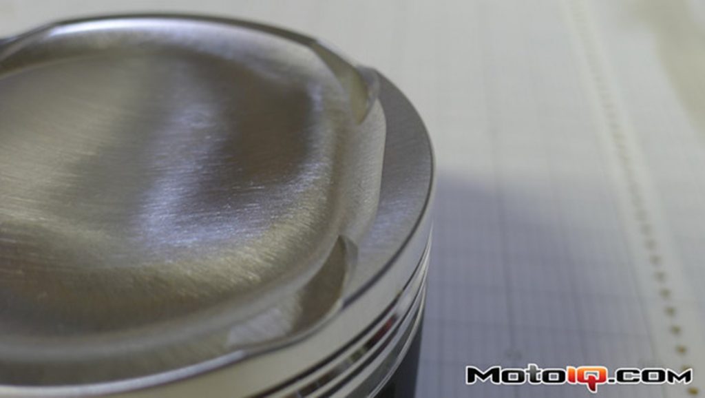
To maintain a safe minimum thickness on the piston crown, the dish in the top of the piston had to be made a little shallower. This reduces combustion chamber volume at Top Dead Center, which raises the compression ratio. Not a great plan if you’re trying to run the most possible boost on crap 91 octane gas. To get the dish volume back, the lip around the top of the bowl was made narrower, as you can see in this picture. This is as narrow as you can go before you start reducing the strength of the bit overhanging the top compression ring, but it’s just enough to get us back down to the laughably old-school 8.5:1 compression that keeps an SR20DET happy.
There’s only one problem with this solution. The smaller lip reduces the effectiveness of the pathetic little quench pads in the SR20’s head.
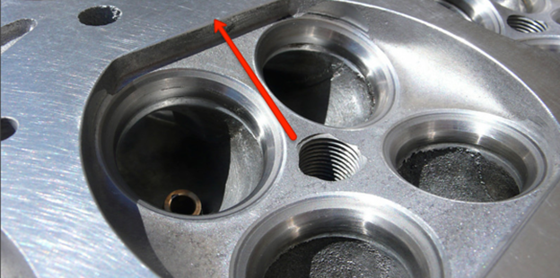
That bit with the red arrow pointing at it is the quench pad. When the piston approaches TDC, the air trapped between the piston and the quench pad gets squished out (that’s why that’s also referred to as squish area sometimes) like ketchup trapped between a table and your fist. This fast-moving squirt of fuel and air comes right as combustion starts and helps speed combustion up. And like I said earlier, faster combustion leaves less time for knock to happen, so we’re all for it.
Since this squish motion is so critically important for knock resistance, we put a little bit of material back on that part of the piston to ensure we still had a full fist hitting that pack of ketchup. As a result, this extra material bumped our compression from 8.5:1 to 8.7:1. Close enough…
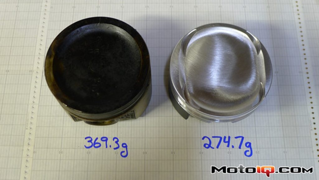
The end result of all this careful design work is almost a 100g weight savings.
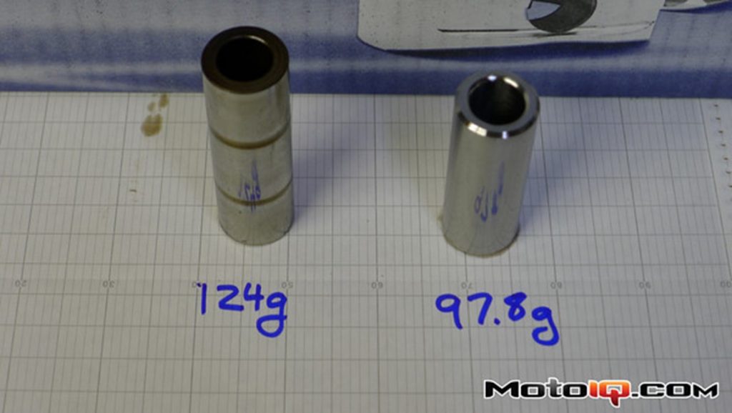
And really, when you count the shorter wrist pin the JE piston is designed to accommodate, the total weight savings is over 120 grams per piston!
Take 120.8g per piston, plus 135.1g per rod, times 4 cylinders, and you have 1.02 kg, or 2.25 pounds less reciprocating weight. That will cause an incredible reduction in reciprocating loads!
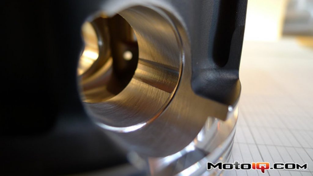
While we’re looking at fancy new pistons, and since I’ve been hanging out with piston nerds a bit, let’s look at some cool details you’ve probably never noticed before. Like this groove in the side of the wrist pin bore. Under extreme loads, the wrist pin is getting pushed on so hard it actually kinda flattens out on top, going slightly D-shaped. The deformation is very slight, but the pin bore clearances are also really tight, so this relief cut is made on each side of the bore so the fat parts of that D have a place to go without actually binding in the bore.
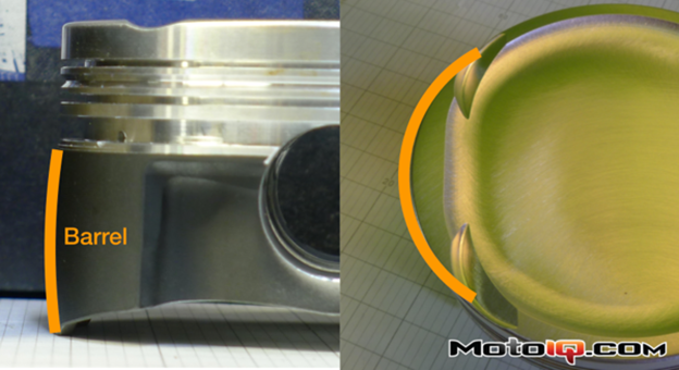
Here’s another cool thing. Pistons aren’t round, and their skirts aren’t straight, because pistons, like everything else in the world if you pay close enough attention, aren’t rigid. The skirts are actually machined into a barrel shape that’s carefully engineered to initially contact the cylinder bore in just a tiny spot. This initial small contact area reduces friction, but more importantly, as side load increases, the piston skirt deforms, bringing more and more of the skirt in contact with the wall. This gradual, cushioned contact reduces piston slap noises and reduces skirt and cylinder wall wear.
Similarly, when viewed from the top, the skirts are machined in an oval shape. This promotes the same gradual contact.
Not only are these amazingly subtle and precise shapes machined into every piston, but JE is able to customize these shapes for each piston order. Their custom piston machining process is so streamlined that if an engine builder is having problems with scuffing or piston slap, JE can re-profile the skirts with a few clicks of a mouse.
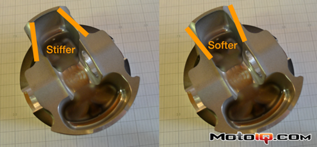
Another fine tuning tool is the shape and position of the skirt supports. The entire support structure of that piston skirt can be fine tuned to ensure they’re stiff enough to protect the piston, but not stiff enough to damage the cylinder wall.
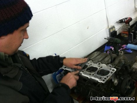
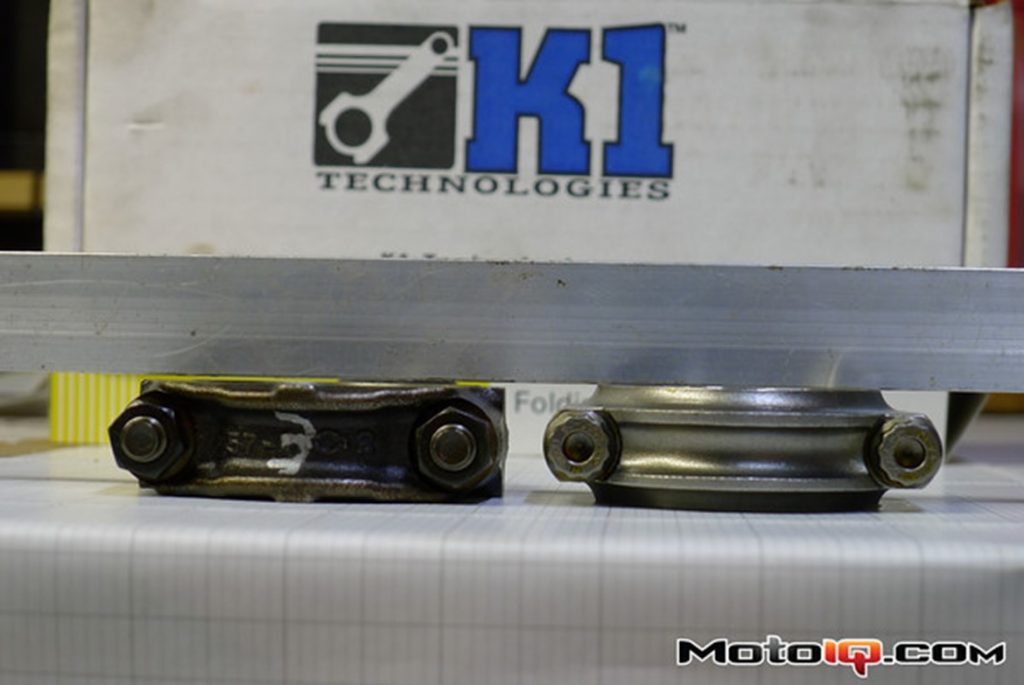
And, while we’re talking about nerds, and things you thought were rigid but really aren’t, let’s talk about machining the block. Over the course of countless SR20 builds, Clark Steppler has realized that the cylinder bores get distorted by a small but meaningful amount by not only the head bolts, but also the bellhousing bolts. If you think about it, this is obvious. Head bolts are torqued hard enough to stretch significantly. If they’re pulling hard enough to stretch the bolt, they’re also pulling hard enough to pull the aluminum block slightly out of shape. An open-deck block won’t have this issue, since top of the bores aren’t attached the part of the block being distorted by the head bolts, but some distortion is inevitable on a closed-deck block like the SR20.
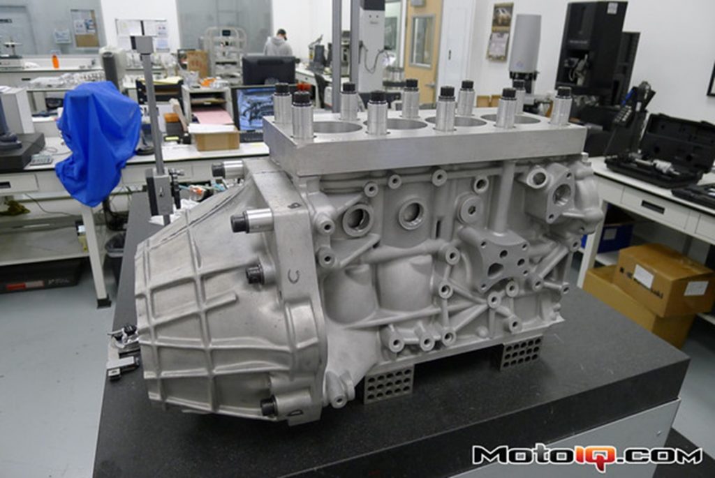
So any time 5523 Motorsports or Jim Wolf have a block machined they first bolt on this deck plate and cut-down bellhousing and torque all the bolts to their final assembly specs to pre-distort the block just as it will be when it’s finally assembled. This way, when the engine is assembled, the bores will get distorted back to their as-machined condition.
The normal process when building an engine is to get the pistons first, then give the pistons and a target piston-to-wall clearance spec to the machine shop when they bore and hone the block. The machinist can then measure your pistons exactly, and hone the bores to exactly the clearance needed for your actual pistons. This eliminates any tolerance stack-up as tiny variations between the piston specs and their as-delivered sizes, and tiny variations in final bore diameter potentially take you outside your target piston to wall clearance.
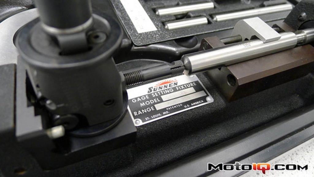
That’s a nice theory anyway, but Chuck the piston nerd doesn’t trust the measurements most machine shops make. His distrust is not of the machinists themselves, but their generally sub-aerospace control of the test conditions. In JE’s test shop, measurements are taken in a temperature controlled room with equipment that is calibrated every few months. When measuring to the ten-thousandth of an inch, the difference in a morning and a mid-day measurement of an aluminum part can actually make a difference, as can a few years of wear and tear on the micrometer used to measure the pistons and the potentially different wear on the bore gauge used on the block.
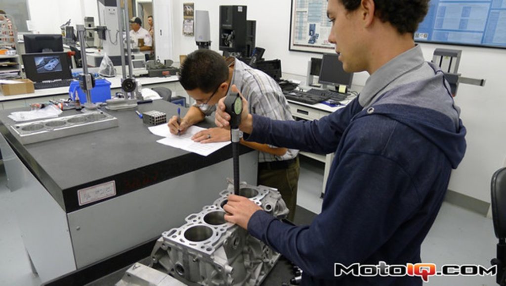
So, at Chuck’s insistence, we took the opposite approach, asking the machine shop to bore the block to 87mm exactly and JE would build pistons to match.
This gave us a good opportunity to double check that machine shop quality control by measuring the block in JE’s clean room. After measuring each bore in 6 places (parallel with and perpendicular to the crank at the top, middle and bottom of the bore), every measurement was essentially within the measuring accuracy of our equipment (a window of about 0.0003″). In other words, dead on. So we can trust our machine shop.
Ok, back to work…