
By Jen Hunter
What do you do when your NB2 Miata with a bolt on supercharger kit and stock engine just isn’t putting down the time you want at the AutoX track on the weekend? Over nights parts from Japan?
Ok, now that I got that out of my system…
When Jacey called asking how he could make his NB2 Miata more competitive, I was really excited. I have always had a soft spot for Mazda sports cars, and this car is no exception. After discussing his power goals and his interest in increased reliability, we came up with a game plan and set to work.
When the 2002 Mazda Miata MX5 arrived at our shop, it had a bolt on Rotrex Supercharger and a stock engine. It also had a Turbosmart Race Port and an AEM EMS4 with a preexisting tune. After driving his NB2 Miata around a little, I agreed that it was very respectable car but not enough for the class he runs in. Plus, who doesn’t want more power?
The Rotating Assembly:
With reliability being the focus of this build, we decided to use JE Pistons. We increased the bore by 0.5mm, which gave us 84mm bore. We changed the compression ratio to 9.0:1. The JE Pistons we chose are 2618 T6 low-silicone alloy with JE Pro Seal piston rings and a 1.0 / 1.2 / 2.8mm ring stack. 2618 T6 is a low-silicone alloy that is extremely strong and can be found in the most high output engines. Due to it’s low silicone content, the piston-to-wall clearance must be a bit bigger than high silicone (4032), as the material expands substantially compared to 4032. 2618 has a very high tensile strength but is more brittle than it’s 4032 counterpart.
The top ring is carbon steel, and hard nitrided, with a barrel face, neutral twist, and it is back cut. The 2nd ring is ductile iron, phosphate coated, napier faced, neutral twist and also is back cut. The oil ring is carbon steel, nitrided SS50U type. We used JE 51 series wrist pins, which are 5115 low-carbon steel, case hardened, straight wall, 97g, 20.0mm (0.787″) diameter, 57.15mm (2.250″) length and 4.5mm (0.180″) wall thickness. We also used JE 0.050″ chrome silicone wire locks.
In addition to the JE Pistons, we chose to use Eagle connecting rods. Eagle rods are a nice, cost-effective option for many engines. These particular connecting rods are standard length (132.95mm; 5.234″), match lightened and balanced. 5523 Motorsports modified the small ends by adding an additional oiling port to better utilize the forced oiling provided by the piston oil jets. 3/8″ ARP 2000 big end bolts clamp the caps to the beams and are torqued by measuring stretch.
Unfortunately, we were so excited to put the engine together we forgot to take any good pictures of the pistons, connecting rods or bearings. Sorry everyone.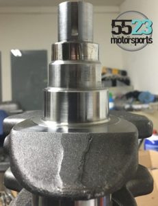
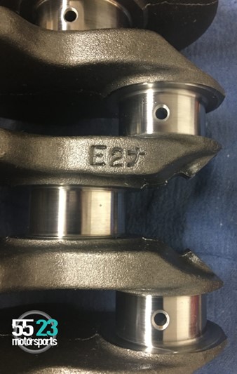
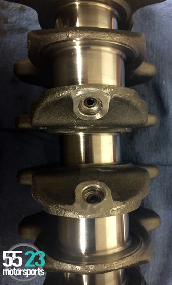
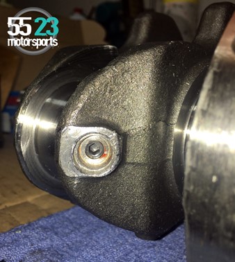
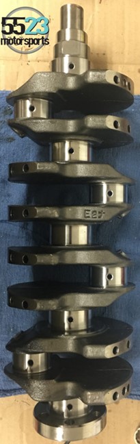
The 85.0mm factory Mazda crankshaft was used for this project. The main journal oiling hole chamfers were exaggerated to help rod bearing oiling, and the rod journal holes were chamfered and de-burred. The chamfer on the oiling holes for the con rods allows for better and more even distribution of oil on the bearing. Chamfering also allows a smoother flow of oil to the journal. The chamfer on the main journal provides a small reservoir for oil, which coincidentally increases the oil pressure fed to the rod bearings as the chamfering is uncovered and then recovered by the engine bearing as the crankshaft rotates. This also eliminates a sharp 90o bend and potential stress risers. Anytime we can perform a simple machining operation that decreases the likelihood of cracking, especially in critical areas such as crankshaft journals, we take the time to do so.
Note the apparent blemishes on the journals. This is common after a crank has been polished. The journals are actually mirror smooth. The polishing operation often leaves discolored bands, bright and/or dark striping that appear to be scratches or grooves. Rest assured, the journals are blemish free.
We then check for crankshaft run-out and straighten as necessary. The tolerance for straightness is less than 0.0005″. A straight crankshaft makes for happy bearings and eliminates bearing damage due to crank run-out. If the short block is assembled with measurable run-out in the crank, irreversible damage can be done to the bearings even by simply rotating the crankshaft by hand. The last machine operation performed is a fine polish of both main and rod journals. This often leaves odd “witness marks” on the journals, which appear to be scratches or discolored bands. This is completely normal; rest assured, these journals are mirror smooth.
The oil gallery ball plugs have been removed and replace with threaded plugs. Removal of the ball plug allows for proper cleaning. This procedure is often overlooked but it is critically important. The bearings in an engine are oiled in the following manner: Pressurized oil from the engine block’s main oil gallery is fed into the main bearings. The main bearing clearance controls system oil pressure, as they are the first internal component fed (after the oil filter). Once the main bearing has been fed, there is nothing re-pressurizing the oil, and the rods are fed through centrifugal force. As the crank rotates, the oil is slung down the oil gallery to the throw (the rod journal). This is a simple, yet elegant, method of lubrication. The rod is oiled more as engine speed increases, which is nice because the rod needs more oil as engine speed rises, yet there are no additional parts to worry about.
The problem with cross-oiling is due to the method by which crankshafts are manufactured. OEM manufacturers, always under pressure to bring manufacturing costs down, will often drill the cross hole through each journal and then connect the main to the rod by drilling from the outside edge of the throw until they intersect with the main journal hole. This is the cheapest and easiest way to drill the galleries. The problem is that there is now a small cavity on each lateral gallery beyond the rod bearing gallery that goes nowhere. This makes a fantastic trashcan. That’s a lot of words to explain why it’s so important to remove these lateral galley plugs for proper cleaning. It’s not uncommon to remove the original ball plugs from a new OEM crankshaft and find metal shavings, dust and cutting oil from the manufacturing process. Reconditioning a used crankshaft is always interesting, as you’ll often remove the plug to find rock-solid sludge that has been compacted simply due to the crank rotating.
A question often asked is “why aren’t you balancing the crankshaft?” The simple answer is that due to its design, an inline 4 cylinder cannot be dynamically balanced like a V6 or V8. We can, however, pay very close attention to the piston/rod assembly weights. Each piston is weighed and compared, and then we “match lighten” all pistons until they equal the weight of the lightest of the bunch. Connecting-rod total weight (rod to rod), connecting-rod rotating weight and reciprocating weight (more on this in a minute) are both treated to the same match lightening procedure.
Hang on, how can something have 3 different weights, you ask? Let me explain. Total weight is easy to understand: We take the whole rod, put it on a super accurate scale and record the weight. The next two require a bit of simple fixturing. The rotating weight (big end weight) is called such because it rotates with the crankshaft. The reciprocating weight (small end weight) is called such because it moves up and down the bore with the piston. The fixturing allows us to isolate either end of the rod by suspending the rod from the opposite end and then putting the end we are measuring on the scale. The rod must maintain level for this measurement to be accurate. Best of all, it’s a simple matter of arithmetic to verify. Reciprocating weight + rotating weight = total weight.
Now, back to the initial balancing question: Due to the firing events happening in 180o intervals, inline 4 cylinder engines are shaky by design. Larger displacement (read, long stroke) inline 4 cylinder engines often employ separate counter-balancer assemblies or counter-shafts in an attempt to dampen these vibrations. These balance shafts (or counter-balance shafts) are usually timed such that they are providing equal and opposite vibrations that complement the 180o firing events. These events occur between the existing 180o events. In other words, if you think about the face of a clock, if a firing event occurs at 12:00, there would be a counter event at 3:00, another firing event at 6:00, another balance event at 9:00, and then we are back to 12:00. The Mazda BP engine does not utilize any counter-balance measures.
The Engine Block:
Once we had the rotating assembly formula set in stone, we set to work removing the BP engine from the car and disassembling the engine itself. After the engine was disassembled, we took measurements and prepared for the required machine work. The block was stripped down, baked, shot blasted and then washed. We then magnafluxed the entire block to verify that there were no cracks. Magnafluxing is a fairly simple procedure that uses an electromagnet and some brightly colored ferrous powder. The block is magnetized, and the powder is dusted over the surface. If there is a crack present, the dust “sticks” to the crack. Once we are assured there are no cracks, we de-bur the entire block, removing sharp edges and any stress risers.
Casting flash is the sharp edge remnants of the production process. It comes from where there are junctions in pieces of the mold. Removal of the casting flash is done to make the block stronger. Ridges formed by the flash are a starting point for cracks in the block and stress fractures.
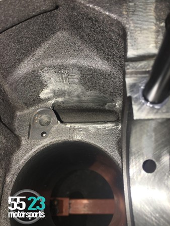
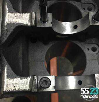
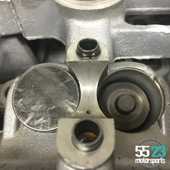
Here is a detail shot of one of the piston oil jet galleries as well as where some casting flash was removed. Note the cross hatching in the main saddle in the foreground.
The block is then bored to approximately 0.003″ (different manufactures use different alloys of iron for their cylinder liners and they all cut a little differently) short of our target finished bore diameter.
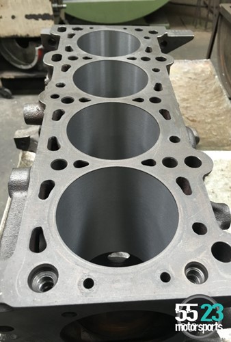
All the machine work excluding the resurfacing has been completed at this point. The cross-hatched cylinder liner finish is quite apparent. If you look closely, you can see the fire ring grooves left from the original headgasket. This is one of the reasons surfacing is so important.
Then it’s over to the CK-10 for honing. This procedure utilizes stone-faced shoes that tear more than they cut. The block is “rough honed” to approximately 0.0005” – 0.001″ of target (again, they all cut a little differently). We then diamond hone to our target. Diamond honing (as the name implies) uses a shoe faced with crushed diamonds, which ultimately produce an extremely uniform and consistent finish. Lastly, we run a plateau brush (commonly referred to as a trash brush) through each bore to remove the microscopic folds created by honing.
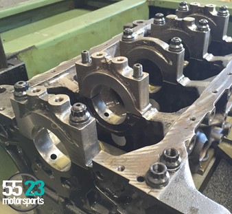
The keen observer will have noticed that one of the main caps has no nuts and is not sitting in it’s installed position. The block is actually clamped in the align honing cabinet. All 5 housings are honed simultaneously. Unfortunately, due to the way in which the block distorts when the caps are torqued down, each housing cuts at a different rate. Basically, you have a couple strokes with the hone, remove the mandrel and then measure each housing. As you approach you target diameter, you have to loosen the caps that are cutting faster so as not to overshoot your target size.
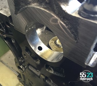
The next operation is align honing the main saddles. This operation is necessary, in this case, because we are utilizing ARP studs. The studs are so strong that they actually distort the main caps, resulting in an egg-shaped main bearing housing (which, needless to say, doesn’t bode well for bearing longevity). We take each main cap and deck it (remove 0.0005″ or so) and then torque the caps onto the block. All of the main bearing housings are honed together, the target being equally sized, and perfectly round housings.
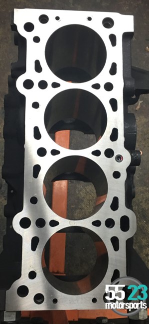
Lastly, we deck the head gasket surface of the block to ensure there is a mirror smooth surface for the MLS gasket. This is a critical step, as MLS gaskets are incapable of sealing imperfections the way a composite gasket can.
All machine work has been completed at this point. The block has been painted with flat black engine enamel and you can also see the 5523 Motorsports screw in cylinder head oil restrictor on the right center of the picture (look for the pink paint mark). The factory restrictor is brass and they will often fall out during the baking process. Threading this port allows us to change the fixed orifice diameter thus altering total oil flow to the cylinder head.
To complement our new JE Pistons and Eagle connecting rods we ordered some King XP Series tri-metal race bearings for the mains and rods. We also ordered ARP main studs, ARP head studs and ARP flywheel bolts. New OEM Mazda piston oiling jets and oil jet valves were also ordered and installed in the new engine.
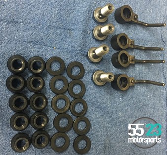
ARP nuts, Blanchard ground flat washers, and brand new OEM piston oil jets and their check valves. It is absolutely imperative that these check valves are replaced whenever building an engine. Oil flows into the bottom of the bolt. If oil pressure exceeds internal spring pressure, the valve opens and allows oil to flow through into the jet. These are 4 more tiny trashcans that can lead to a very expensive pile of broken engine! Like oil coolers, it’s nearly impossible to properly clean these out (especially if they’ve come from an engine that had a bearing failure that resulted in tiny fleck of bearing material being pumped throughout the lubrication system).
The crankshaft was then installed in the block. The main caps, which utilize ARP main studs were tightened to spec and ready for the pistons and connecting rods.

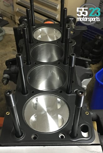
Once the crankshaft was installed, the pistons and rods were assembled and installed into their respective cylinders. The head studs were installed and the short block was ready for the cylinder head to be installed.
To help with oiling, Jacey brought us a new oil pump. This new oil pump has inner and outer rotors made of 4340 chromoly steel. When we received the new oil pump we discovered that it needed a lot of attention. We found the pump was full of aluminum chips and dirt, yet again confirming that new parts require just as much cleaning as dirty grimy used parts. We also found one of the welch plugs was installed improperly. The pump was completely disassembled and cleaned. We then de-burred the complete housing and re-profiled the discharge port, which was riddled with sharp edges and hard corners. The oil pressure relief valve was then shimmed to increase total pump pressure output. We removed all the welch plugs and taped the holes for threaded plugs. When building an engine, it’s the small things that are frequently overlooked. The minimal effort and cost to replace something that could have a great effect on your engine, such as oil jets or properly cleaning engine components inside and out, are always worth the little amount of insurance they add.
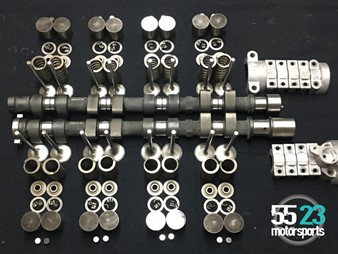
The Valvetrain:
The valvetrain is an important part of an engine. It is highly complex on multiple levels. Proper valvetrain design is imperative because changing just one component without consideration for how it will interact with the rest of the parts can throw off the delicate balance.
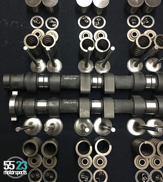
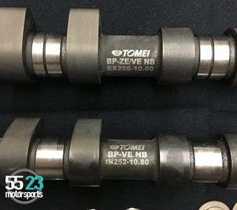
For the BP18 engine with VVT, there are limited choices for camshafts. The Tomei PonCam camshafts are the only off-the-shelf option. These camshafts are mechanical and ground on a smaller base circle. This is a trick utilized to allow us to run a cam profile with more lift.
We also use Tomei’s lifter bucket conversion to move the lash shim from the stock location (larger diameter shim on top of the bucket, between the cam and the bucket) to underneath bucket between the valve stem tip and the bucket. This is also necessary with the additional duration as the nose of the cam lobe will run off the edge of the original shim resulting in catastrophe.
The intake cam has 252o duration and 10.8mm lift, and the exhaust has 262o and 10.0mm lift.
In addition to the Tomei PonCam, custom 5523 Motorsports valves were designed. The intake valves are stainless steel and 1.0mm oversized. The exhaust valves are stainless steel and 1.0mm oversized. In addition to the custom valves, this engine uses custom 5523 Motorsports manganese bronze valve guides that have been diamond honed.
The Cylinder Head:
Once the short block was completed and the valvetrain components carefully selected, it was time to focus on the cylinder head itself. The BP-VE cylinder head was given the 5523 Motorsports race treatment. We started with removing the stock pot-metal valve guides and replacing them with 5523 Motorsports Manganese Bronze guides. These guides significantly increase heat transfer from the valve stem into the cylinder head. Then the cylinder head is prepped for some extensive porting work. We start by measuring each combustion chamber, and then scribing both the intake and exhaust gasket outlines onto their respective flanges.
The intake ports are gasket matched and tapered. We then knife edge the port divider to help smooth out flow. The bowls are blended into the roof of the port, and the short-side radius is re-profiled and blended into the port floor. The intake-valve guides are then relief cut and blended into the port roof. You may have noticed that the intake ports aren’t polished. There is a very good reason for this: A smooth port wall creates surface tension significant enough that the atomized fuel is actually pulled out of suspension and pools on the smooth port wall. We intentionally leave some tooth, as it provides just enough turbulence to help keep the fuel atomized. Some of you may be familiar with the term “wall wetting.” With a port injected engine, it is impossible to keep the fuel from wetting the port walls. It’s a fact of life; we even tune for it. That said, we also make sure we aren’t helping to promote wall wetting.
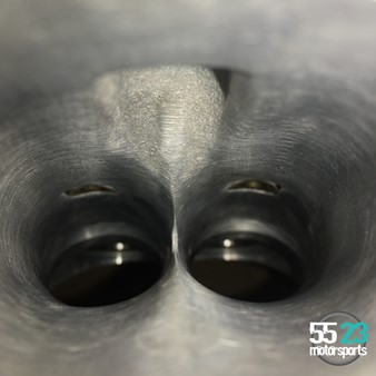
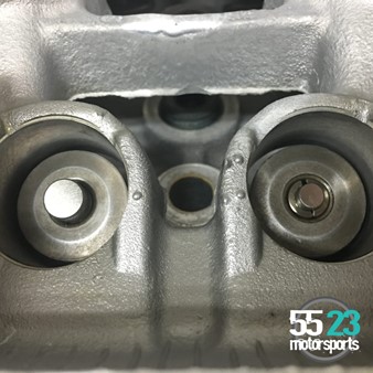
The exhaust side receives the same treatment with the exception of the guides. Due to the port design, the guide cannot be blended into the roof without removing enough material to significantly weaken the surrounding aluminum. We also want to avoid porting into a water jacket.
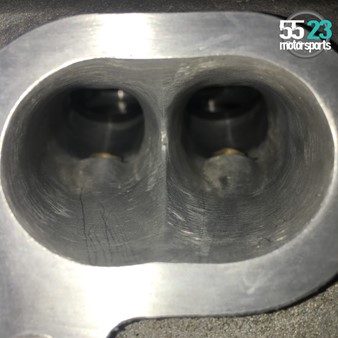
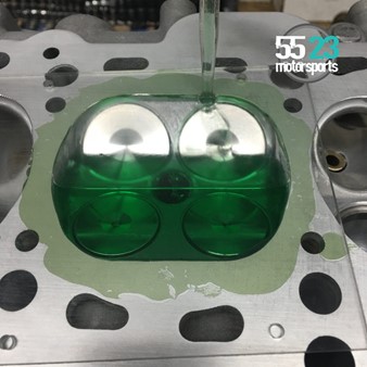
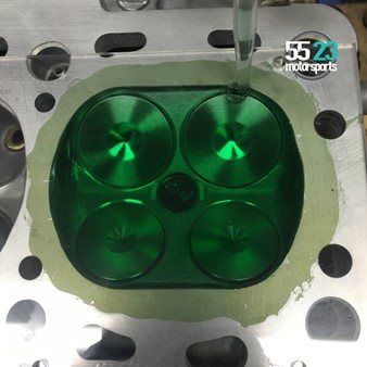
Valve seats were then cut to accommodate 1.0mm oversized 5523 Motorsports stainless steel valves. You can also see some combustion chamber profiling that was utilized to equalize chamber volume cylinder to cylinder.
The head was then resurfaced. We are very careful to remove only the minimum material required to give us a perfectly flat and true surface. We measured the overall height of the head at the very beginning to ensure that after surfacing, we’d still be within spec. Removing too much material results in decreasing the combustion chamber volume (which raises compression) as well as skewing crank-to-cam timing. More about timing below.
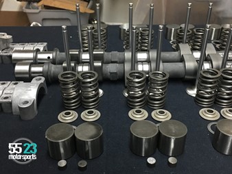
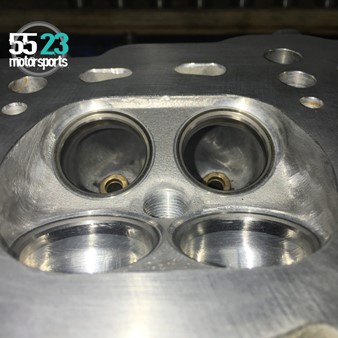
5523 Motorsports custom valves have been installed in the BP18 cylinder head and lash measurements have been taken.
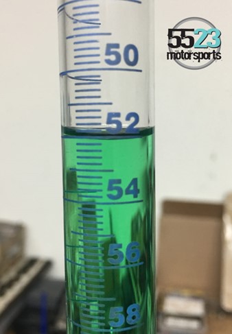
Validating combustion chamber volume after all machine work is critical. The volume of the combustion chamber is a key part of determining the compression ratio of an engine. If combustion-chamber volume is different from cylinder to cylinder, each cylinder will then produce different amounts of energy. This can cause an imbalance of work, which means one cylinder may be working harder than the others while some are just there for the ride. This can rob the engine of power and add additional stress to the engine.
The correct size valve lifters have been installed, and the cylinder head is ready for camshaft install.
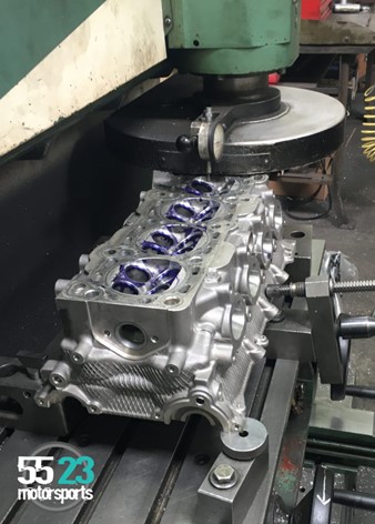
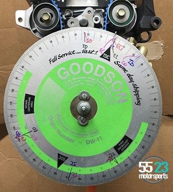
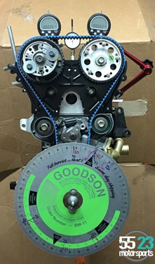
Before the cylinder head on this BP-VE engine is sealed up, the Tomei PonCam must be degreed. Degreeing cams, simply put, is verifying that the cams are in sync with the rest of the engine. It’s always important to verify that the rise and fall of the pistons coincide with the opening and closing of the valves. Since the camshafts control when the valves open and close, verifying that something like a mis-marked cam or crank gear or a keyway out of position isn’t going to create issues with the engine running properly, and it is easier to take care of now rather than when the engine is installed in the car. Even a degree or two of misalignment can create issues during engine operation. Whenever you’ve removed material from the block, head or both; you’ve altered the camshaft-to-crankshaft centerline. This can cause big problems with regard to cam timing. Degreeing the engine allows us both to measure and then alter static cam timing. This procedure is carried out with the variable intake cam phaser in it’s home (no advance) position as well as in the full-advance position. This is then compared to the manufacturer’s listed specifications.

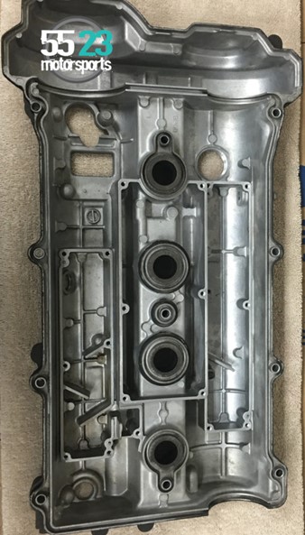
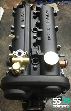
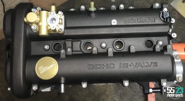
The valve cover is disassembled, cleaned and then reassembled before install on the cylinder head. This ensures there is no debris that will find its way into the freshly build engine.
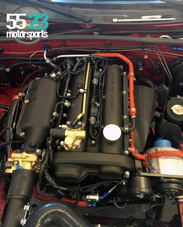
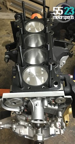
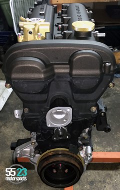
Now the engine is finally assembled and ready to start its new life in Jacey’s NB2.
Stay tuned. In our next installment, we will go over the installation of the engine and additions to the car.